

6 minutes read time
Effective thermal management plays a critical role in ensuring that electronic devices and systems operate consistently and safely over their intended lifespan. Excessive heat is one of the leading causes of failure in electronics, leading to issues such as degraded performance, shortened component lifespans, and failures.
This article explores the importance of thermal management in electronics and provides actionable strategies to enhance reliability through effective heat dissipation techniques.
Why Thermal Management Matters
For every 10°C increase in operating temperature, the failure rate of electronic components approximately doubles – the Arrhenius equation.
Electronics generate heat during operation due to power consumption and inefficiencies in components like semiconductors, resistors, and power converters. If this heat is not managed effectively, it can lead to:
- Component Degradation: High temperatures accelerate the aging process of components; high temperatures increases chemical and physical process activities e.g., oxidation, diffusion, material degradation.
- Performance Issues: Overheating can cause components like ICs to prematurely activate thermal shutdown to prevent damage, leading to inconsistent operation.
- Failure Risks: Excessive heat can result in permanent damage, such as melted warped or burned PCBs.
Effective thermal management ensures that heat is dissipated efficiently, maintaining optimal operating conditions and prolonging the life of electronic systems.
Strategies for Effective Thermal Management
1. Optimise PCB Design for Heat Dissipation
- Why It Matters: The printed circuit board (PCB) layout significantly impacts thermal performance. Proper design can channel heat away from critical components.
- How to Do It:
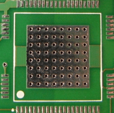
- Use thermal vias to transfer heat from the top layer to the bottom layer, where it can dissipate more effectively.
- Create large copper planes sufficiently under heat-generating components to act as heat sinks.
- Use wide and short PCB trace for high current paths to reduce voltage drops.
- Ensure proper spacing between components to prevent localised hotspots.
- Example: A D2PAK Schottky diode with forward current 10A continuous dissipating 5W, can be placed near a copper plane with multiple thermal vias under.

2. Use Heatsinks
- Why It Matters: Heatsinks provide a large surface area for heat dissipation, which increases heat transfer to lower temperature.
- How to Do It:
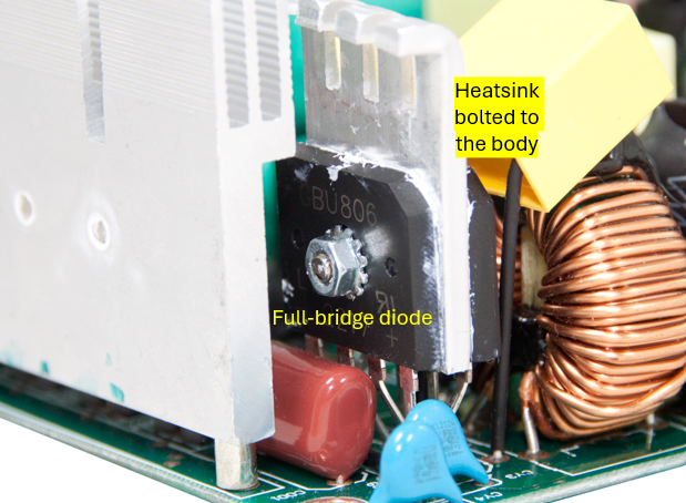
- Select a heatsink material with high thermal conductivity, such as aluminum or copper.
- Ensure proper contact between the heatsink and the component using thermal paste or thermal pads.
- Choose heatsinks based on the component’s power dissipation and cooling requirements.
- Example: A full-bridge rectifier at AC/DC converter input dissipating 5W can use a finned aluminum heatsink to maintain safe operating temperatures.
3. Implement Active Cooling
- Why It Matters: In high-power applications, passive cooling may not suffice. Active cooling mechanisms, such as fans or liquid cooling, can significantly enhance heat dissipation for an extra cost.
- How to Do It:
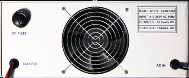
- Use fans to force air over heatsinks, increasing heat transfer efficiency.
- Employ liquid cooling systems in high-performance devices to transfer heat away from critical components.
- Example: High-power battery chargers often use fans to reduce internal ambient temperature from heat generated by N-MOSFETs, freewheeling Schottky diodes, and transformers.
4. Select Heat-Resistant Materials
- Why It Matters: Components and materials with high-temperature tolerances can sustain performance in demanding environments.
- How to Do It:
- Choose resistors made of metal film or metal foil especially for high dissipating applications.
- Select ceramic capacitors with dielectric rating X7R or X8R or X9R to allow extreme temperature operations.
- Choose electrolytic capacitors with high-temperature ratings (e.g., 125°C or higher) for power supply circuits.
- If FR4 not sufficient, use PCBs with high-temperature substrates, such as FR-4 High Tg of 180°C or aluminium, to prevent warping.
- Example: Automotive driving lights consist multiple high-power LEDs dissipating about 200W in total. The PCB often uses aluminium to dissipate more efficient and withstand high temperature long term.

5. Utilise Thermal Interface Materials (TIMs)
- Why It Matters: TIMs, such as thermal pastes and pads, improve the heat transfer between components and heatsinks by filling microscopic air gaps. These air gaps are not good heat conductors, therefore must be minimised.
- How to Do It:
- Apply a thin, even layer of thermal paste between the CPU and its heatsink.
- Use thermal pads for components where precise application of paste is challenging.
- Example: In consumer electronics, TIMs are commonly used between processors and heatsinks to optimise thermal conductivity.

6. Monitor and Control Temperature
- Why It Matters: Real-time temperature monitoring and control help prevent overheating and ensure safe operation.
- How to Do It:
- Use temperature sensors, such as thermistors to monitor critical points.
- Implement thermal protection circuits to shut down the system if temperatures exceed safe limits.
- Alternatively, use digital PID controller to control the temperature whose derating behaviour can be adjusted for smooth transition.
- Example: Power supplies often include thermal shutdown mechanisms to protect components from excessive heat.
Common Mistakes to Avoid
- Ignoring Heat Sources During Design:
- Overlooking heat generation in the initial design phase can lead to costly redesigns and reliability issues.
- Using Inadequate Thermal Interfaces:
- Poorly applied thermal paste or low-quality TIMs can reduce heat transfer efficiency.
- Underestimating Environmental Conditions:
- Failing to consider ambient temperature and airflow can compromise cooling performance.
Benefits of Effective Thermal Management
- Improved Component Lifespan: Reducing operating temperatures slows degradation, ensuring longer operational life for components.
- Enhanced System Performance: Proper cooling allows systems to operate at full capacity without throttling or thermal shutdowns.
- Increased Reliability: Systems with robust thermal management are less prone to unexpected failures, reducing maintenance costs.
- Regulatory Compliance: Many industries require devices to meet specific thermal performance standards.
Conclusion
Thermal management is a vital aspect of ensuring reliability in electronics engineering.
By optimising PCB layouts, using heatsinks, implementing active cooling, and selecting high-temperature-rated materials, engineers can mitigate the risks associated with excessive heat. Additionally, employing thermal interface materials and real-time monitoring ensures efficient heat transfer and safe operation.
Investing in effective thermal management strategies not only enhances product reliability but also builds customer trust and satisfaction. By prioritising thermal considerations during design and testing, engineers can create durable, high-performance electronic systems that stand the test of time.

Leave a comment